When working with engineering parts, confusion between metric and imperial measurements is one of the most common—and costly—sources of error. A component specified in millimeters may appear similar to one measured in inches, yet small differences in size can lead to misalignment, poor fit, or premature wear. For engineers, buyers, and technicians alike, understanding how these two systems compare is essential for avoiding mistakes and ensuring reliable performance.
This challenge becomes even more pronounced in global supply chains, where design may follow metric standards while manufacturing, tooling, or maintenance relies on imperial measurements. In these situations, metric-to-imperial size comparisons for engineered tubing components help illustrate how dimensional clarity supports proper component selection and long-term equipment reliability.
Rather than treating metric and imperial units as interchangeable, it is more effective to understand how they relate—and where critical differences can arise.
Understanding the Two Measurement Systems
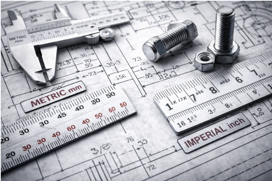
The metric system is based on powers of ten, making conversions straightforward and consistent. Length is typically measured in millimeters or centimeters, and dimensions scale logically as values increase or decrease.
The imperial system, on the other hand, uses inches, feet, and fractions that are less intuitive to convert. While widely used in certain regions and legacy industries, imperial measurements require greater care when precision matters.
Both systems are valid, but problems occur when assumptions are made without proper conversion or verification.
Why Direct Conversion Is Not Always Enough
A common misconception is that converting units automatically resolves compatibility issues. In practice, this is not always true. Nominal sizes, tolerances, and industry conventions often differ between metric and imperial components.
For example:
- A “1-inch” part may not be exactly 25.4 mm in functional terms due to tolerance standards.
- Metric components are often designed around round-number millimeter values, while imperial parts rely on fractional inches.
- Wall thickness, internal diameter, and fit classes may follow different conventions depending on the system used.
These differences mean that two parts with similar converted dimensions may still behave differently in assembly or operation.
Visualizing Size Differences in Real Applications
One effective way to reduce confusion is to visualize size differences using consistent reference points. Comparing diameters, lengths, or clearances side by side—rather than relying solely on numbers—helps reveal subtle but important distinctions.
For cylindrical parts such as tubes, rods, or sleeves, small dimensional mismatches can affect alignment, insulation gaps, or thermal expansion behavior. Understanding how a metric-specified component compares physically to its imperial counterpart helps prevent costly trial-and-error during installation.
Tolerances and Standards Matter
Measurement systems are closely tied to standards. Metric components often follow ISO-based tolerances, while imperial parts may follow ANSI or other regional standards. These standards define acceptable variation and influence how parts fit together.
Ignoring tolerance standards can lead to assumptions that parts are interchangeable when they are not. This is particularly important in high-temperature or precision environments, where dimensional stability and repeatability are critical.
In testing and evaluation contexts, dimensional behavior of industrial crucible materials under standard measurement systems highlights how consistent measurement references are necessary to interpret results accurately across different unit systems.
Practical Tips for Comparing Metric and Imperial Parts
To minimize errors when comparing components across measurement systems, consider the following practices:
- Always confirm whether dimensions are nominal or actual.
- Check tolerance standards associated with each measurement system.
- Avoid rounding converted values unless specifications explicitly allow it.
- Use visual references or scale drawings whenever possible.
- Communicate clearly which system is being used in documentation and procurement.
These steps reduce ambiguity and help ensure that parts perform as expected once installed.
Why This Matters for Equipment Reliability
Dimensional mismatches rarely cause immediate failure. Instead, they often lead to gradual issues such as uneven stress distribution, accelerated wear, or thermal distortion. Over time, these problems reduce equipment lifespan and increase maintenance demands.
By understanding how metric and imperial sizes truly compare—and respecting the standards behind them—engineers and decision-makers can improve fit, function, and reliability across systems.
Final Thoughts
Comparing metric and imperial sizes is more than a mathematical exercise. It requires awareness of standards, tolerances, and real-world behavior. In engineering applications, small dimensional differences can have outsized effects.
A practical, informed approach to measurement comparison helps bridge gaps between design, manufacturing, and maintenance. Ultimately, clarity in dimensions supports better decisions, fewer errors, and more reliable equipment performance.